step 5
Fig16 shows the LCD and Circuit board combo removed. 4 screws are involved.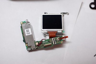
Fig 17 shows the hidden connector that needs to be removed. You just bend the top orange connector back, but don't break the solder.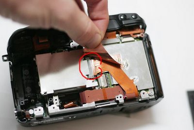
Fig 18 shows the sensor and hottmirror flipped over.. not disconnected. Three more scres removes the hot mirror and plastic holder. There is also a rubber gasket, a simple exacto knofe removes the hot mirror from the plastic. Fig 19.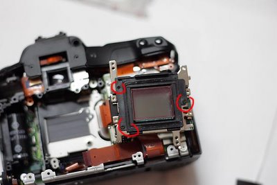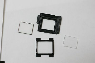
posted by Soren at 9:51 PM
![]()

0 Comments:
Post a Comment
<< Home