step 4
Then Fig 11 shows the metal plate being removed.
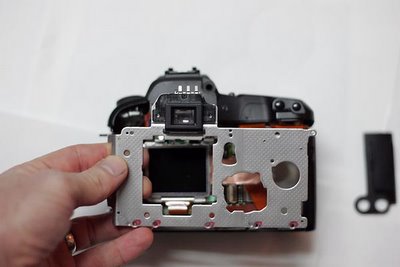
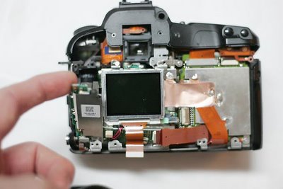
Fig 12 shows three more ribbons to be removed. The bottom left brown bit has a tendency to drop into the camera... At least for me. I stopped paying attention, so I may have missed a screw here.
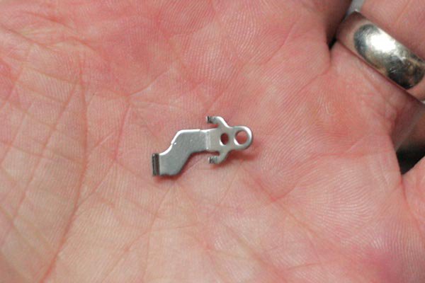
I also dound a spare part! don't know where fig 13 goes...
Fig 14 shows an "L" shaped circuit board being removed.

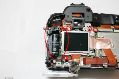
Fig 15 shows the dangerous capacitor for the flash.. Never touch this.. I did it once with a disposable camera and threw it accross the room after is zapped me, I am guessing this one might kill you. 15 also shows the screws to remove so the LCD screen can be removed.
posted by Soren at 9:46 PM
![]()

0 Comments:
Post a Comment
<< Home